In this lecture, we are going to learn about the 8237 DMA Controller. The 8237 pin configuration, 8237 Block diagram, 8237 operating modes, and DMA data transfer modes are in detail. so let’s start with the introduction of the DMA controller.
Introduction
In I/O data transfer, data is transferred by using the microprocessor. The microprocessor will read data from the I/O device and then will write data to memory. In this case, there are two operations for single data transfer.
If the data is less then the microprocessor will not waste its time; transferring data from I/O to memory or back, then suppose, the data is huge, then the transfer rate from I/O to memory or back will slow down because of microprocessor intervention.
In such case, to speed up the process of transferring the data, we can think, can I/O have direct access to memory?; and the answer is yes. It can have direct memory access (DMA) but under supervision. The device which supervises, data transfer is named a DMA controller.
8237 DMA Controller
8237 is a high-performance programmable DMA controller. Some of the important features of 8237 DMA controllers are mentioned below:
Features of 8237 DMA Controller:
- It provides various modes of Direct memory access (DMA).
- It provides on-chip four independent DMA channels. The number of channels can be increased by cascading DMA controller chips.
- Each channel can be used in auto initialization mode.
- It can transfer data between two memory clocks in DMA mode i.e. memory to memory transfer.
- In memory-to-memory transfer, a single word can be written into all locations of memory blocks.
- The address of memory is either incremented or decremented after each DM cycle depending upon the mode.
- The clock frequency is 3 MHz (8237 DMA C0ntroller) or 5 MHz (8237-2 DMA Controller).
- The data transfer rate is very high i.e. 1.6 Mbytes/second for 8237-2 at 5 MHz.
- Directly expandable to any number of channels. It doesn’t require any additional chip for cascading. There are no limitations in cascading.
- The DMA can be requested by setting an appropriate bit for the request register.
- It provides compressed timings to improve the throughput of the system. It can compress the transfer time to two cycles (2s).
Also Read : 8254 programmable interval timer
Pin Configuration of 8237 DMA Controller
The pin configuration of the 8237 DMA controller is shown in the below figure. Also, we have discussed the pin description of each pin in very detail.

| Symbol | Description |
|---|---|
| CLK | This is the clock input line ignored in slave mode. In master mode, this signal controls all internal and external DMA operations. The data transfer rate depends upon the frequency of this signal. |
| \mathbf{\overline{CS}} | In slave mode, this signal is generated by the address decoder to select the 8237 chip for communication between the CPU and 8237. In master mode, this signal is ignored. |
| Reset | It is an asynchronous input line. This signal clears the command, status, request, and temporary register and forces 8237 into slave mode. |
| READY | In master mode, this signal is used to add wait states into the DMA cycle. |
| HRQ | It is a hold request output line. It is connected to hold the CPU input. it is used to request control of the system bus. |
| HLDA | It is a hold acknowledge input line. This signal is generated by the CPU. In response to this signal, the 8237 gains control of the system bus and enters master mode. |
| \mathbf{\overline{IOR}} | It is an active low bi-directional tristate line. In slave mode, it acts as an input line and is used to read the contents of the 8237 register. In master mode, it acts as an output line. This signal is generated during the DMA cycle to read data from the I/O device. |
| \mathbf{\overline{IOW}} | It is an active low bi-directional tristate line. In slave mode, it acts as an input line and is used to write the contents to the 8237 register. In master mode, it acts as an output line. This signal is generated during the DMA read cycle to write data into the I/O device. |
| A0 – A3 | These are bi-directional, address lines. In slave mode, these lines act as input lines, used to select one of the registers of 8237. In master mode, the 8237 provides lower bits of memory address on these lines. |
| A4 – A7 | These are tristate address output lines. These lines are tri-stated in slave mode. In master mode, the 827 transfers bits of memory address on these lines. |
| \mathbf{\overline{MEMR}} | It is an active low tristate output line. it is tri-stated in slave mode. In master mode, this signal is generated during the DMA read cycle or during memory to memory transfer cycle to read the contents of source memory. |
| \mathbf{\overline{MEMW}} | It is an active low tristate output line. it is tri-stated in slave mode. In master mode, this signal is activated during the DMA write or during the memory-to-memory transfer cycle to write data into destination memory. |
| DB0 – DB7 | These are bi-directional tristate buffered data lines. In slave mode, these lines are used to transfer data between the CPU and 8237 registers. In master mode, these lines act as address output lines. The 8237 places a higher byte of address on these lines during DMA cycles. |
| DREQ0 – DREQ3 | These are asynchronous DMA channel request lines used by the peripheral. The polarity of each signal is programmable i.e. these lines can be used as either active high or active low input. DREQ must be maintained until the corresponding DACK is activated. |
| DACK0 – DACK3 | These are DMA acknowledged output lines. The polarity of each line is programmable. The signal indicates that the requesting peripheral has been granted for the DMA cycle. |
| \mathbf{\overline{EOP}} | End of Process: It is an active low bi-directional signal This line is also used to terminate the DMA cycle. The DMA cycle can be terminated by pulling \mathbf{\overline{EOP}} input low. The 8237 also generates an EOP pulse, when the terminal count for any channel is reached. |
Also Read : 8259A Programmable Interrupt Controller
8237 DMA Controller Block Diagram
The block diagram of the 8237 DMA controller is shown in the below figure. It consists of logic blocks and internal registers.

Types of Registers in 8237 DMA Controller
There are 12 types of registers in 8237 DMA Controller. It contains 344 bits of internal memory in the form of registers.
1. Current Address Register
- Each channel has a 16-bit current address register.
- This register holds the address of the memory location to be accessed during the current DMA cycle. The address stored in this register is automatically incremented or decremented after each transfer.
- It is a read-and-write register.
- It is divided into two parts: lower byte and higher byte.
- In auto initialization mode, it is initialized automatically with the original address after \mathbf{\overline{EOP}} signal.
2. Current Word Register
- Each channel has a 16-bit current word count register.
- The original value stored in this register indicates the number of bytes to be transferred.
- The word count is decremented after each transfer. The current count indicates the number of pending transfers.
- When the count value in the register goes to zero, a TC will be generated. it is a read-and-write register. It is also divided into two parts: lower byte and higher byte.
- In auto initialization mode, this register is initialized automatically with the original count value after \mathbf{\overline{EOP}} signal.
3. Base Address Register
- Each channel has a 16-bit base address register.
- It is a write-only register.
- It holds the original value of the address during all MDA transfers i.e. the contents of this register are not updated during DMA transfer.
- When \mathbf{\overline{EOP}} is activated, the 8237 transfers contents of base address registers into the current address register in auto initialization mode.
- This register is written along with the current address register during initialization. The format is the same as the current address register.
4. Base Count Register
- Each channel has a 16-bit base word count register.
- It is a write-only register.
- It holds the original count value during all DMA cycles i.e. the content of this register are not updated during DMA transfers.
- When \mathbf{\overline{EOP}} is activated, the 8237 transfers contents of this register into the current word register in auto initialization mode.
- This register is written along with the current address register during initialization. The format is the same as the current word register.
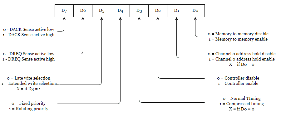
5. Command Register
- It is an 8-bit control register. It is a write-only register.
- This register is cleared by a reset signal. It is used to initialize operation modes of 8237.
- The format of the command register is shown in the below figure.
6. Mode Register
- It is an 8-bit write-only register.
- It is used to set the operation modes of the 8237 DMA controller.
- Each channel has a 6-bit mode register.
- All registers are cleared by the reset signal. The format of the mode register is shown below.
7. Request Register
- It is an 8-bit write-only register.
- It is used to request DMA through software. Each channel has a request bit associated with it in the 4-bit request register.
- Each register bit is set or reset separately under software control The request is automatically cleared after TC. It is also cleared by external \mathbf{\overline{EOC}} signal.
- This register is cleared by a reset signal.
- In memory-to-memory transfer, the software request for channel 0 should be set. The format f the request register is shown in the figure below.
8. Mask Register
- It is an 8-bit write-only register.
- It is used to mask out the channel DMA request.
- In normal mode, the mask bit is set automatically after TC. It is not affected by auto initialization mode.
- The reset signal sets the mask bit of all channels i.e. it disables all channels.
9. Status Register
- It is an 8-bit read-only register.
- It indicates which channels have reached a terminal count and which channels have pending DMA requests.
- Bits 0-3 are set every time a TC is reached by that channel or an external EOP signal is applied.
- These bits are cleared automatically on reading the status register and upon reset signal.
- Bits 4-7 are set whenever their corresponding channel is requesting service.
10. Temporary Register
- This register is used to hold data during memory-to-memory transfer.
- It is an 8-bit read-only register.
- The microprocessor can read the last byte of memory to memory transfer.
- It is cleared by a reset signal.
11. Clear First/Last FLip-Flop
- This command is used to reset the internal first/last flip-flop.
- After issuing this command, the microprocessor can access the lower byte of any 16-bit register. The F/L flip-flop is toggled after each read or write 16-bit register.
12. Master Clear
- It is a software reset command.
- It clears command, status, request, temporary register, and F/L flip-flop.
- It sets the mask register and forces the 8237 DMA controller into slave mode
13. Software Commands
- These are additional special write-only software commands.
- These commands do not require a specific data pattern. i.e. writing only data corresponding to the address enables such commands.
Software Command Codes

Also Read : 8255 PPI (Programmable Peripheral Interface)
8237 DMA Data Transfer Modes
The 8237 DMA controller can be operated in four DMA modes.
| Sr. No. | DMA Data Transfer Modes |
|---|---|
| 1. | Single Transfer Mode |
| 2. | Burts or Block Transfer Mode |
| 3. | Demand Transfer Mode |
| 4. | Cascade Mode |
Operating Modes of 8237 DMA Controller
There are 5 types of operating modes in the 8237 DMA Controller.
1. Auto initialization Mode
- In this mode, the original values of the current address and current word count registers are automatically restored from the base address and base word count registers of that channel following \mathbf{\overline{EOP}}.
- The mask bit is not set when the channel is in auto initialization mode.
2. Priority Modes
- The 8237 provides two priority modes.
- Fixed Priority Mode
- Rotating Priority Mode
- These modes are similar to the 8257 priority mode
3. Normal Mode
- In this mode \mathbf{\overline{Read},(\overline{IOR} and \overline{MEMR})} pulse is activated.
- The minimum length of the DMA cycle is 3S.
4. Extended Write Mode
- In this mode, \mathbf{\overline{Write},(\overline{IOW} and \overline{MEMW})} and \mathbf{\overline{Read},(\overline{IOR} and \overline{MEMR})} pulse is activated.
- The minimum length of the DMA cycle is 3S but one clock cycle is wasted.
5. Copmress Timing Mode
- In order to achieve even greater throughput the 8237 can compress transfer time to two clock cycles.
- In extended write mode, the one clock cycle is wasted, in compressed timing mode that wasted cycle is eliminated.
- The minimum length of the DMA cycle is 2S.
Frequently Asked Questions(FAQs)
What is the 8237 DMA controller?
8237 DMA Controller is a peripheral core for microprocessor systems. It controls data transfer between the main memory and the external systems with limited CPU intervention.
Is 8237 and 8257 DMA the same?
The difference between 8237 and 8257 is that 8237 provides better performance than 8257.
What is the 8237 DMA Controller used for?
It is a device to transfers data directly between the I/O device and memory without through the CPU. So it performs a high-speed data transfer between the memory and the I/O device.
What are the 3 registers in the 8237 DMA controller?
DMA controllers contain three registers: address, word count, and control registers.
Is DMA synchronous or asynchronous?
Asynchronous
Important Links