
In this lecture, we are going to learn about the Radar antenna, types of radar antenna, and important parameters of the radar antenna in detail. So let’s start with the introduction of radar antennas.
Introduction of Radar Antenna
- The purpose of this article is to provide the introduction of the Radar Antennas, Types of Radar antennae, and important parameters of Radar antennae.
- A Radar Antenna either receives energy from an electromagnetic field or radiates electromagnetic waves produced by a high-frequency generator.
- The types of Radar antenna used in the radar system mainly depend upon the application of the radar.
- The Antenna used normally in radar applications is different from the antenna used in communication systems.
- Radar antenna with shaped directive pattern can be scanned either mechanically or electrically.
- In general, an Antenna is a transmission device or transducer between a guided wave (transmission line) and a free space wave or vice versa.
- The basic parameters of an antenna will be discussed in the brief in the following sections.
- The radar antenna acts as a transducer, which converts electrical pulses from the transmitter to the free space in the form of EM waves and receives the reflected EM signals from the target in free space, and converts them into an electrical signal.
- Most radars, as we know are operating on the microwave frequencies region. So the main advantage of microwave frequencies for radar application is that an aperture of relatively small physical size but t s quite large enough in terms of wavelength can be obtained.
- The antenna having high gain with narrow beam widths is possible at microwave frequencies.
Also Read: Doppler Effect | Derivation of Doppler effect formula
Parameters of Radar Antenna
The important parameters of radar antenna discussed here, in brief, are as follows:
- Directivity or Directive gain
- Power gain
- Effective receiving aperture
- Polarizations
- Side lobes
- Front to Back ratio
- Beam efficiency
1. Directivity or Directive gain
- The directivity of an antenna is given by the ratio of the intensity of the maximum radiation (power per unit solid angle) u(θ, Φ) mass to the average radiation intensity Uav(average over a sphere) or it may be defined as at a certain distance from the antenna the directivity may be expressed as the ratio of the maximum to the average Poynting vector.
\mathbf{G_D=\frac{Maximum\,radiation}{Average\,radiation}}
\boxed{\mathbf{G_D=\frac{ u(θ,Φ)_{max}}{U_{av}}}}
- The smaller the beam’s solid angle, the greater the directivity.
- The ability of a radar antenna to concentrate energy in a particular direction is known as Gain.
- The directive gain may be written as the average radiation intensity over a solid angle of 4\pi radians is equal to the total power radiated divided by 4\pi
\boxed{\mathbf{G_D=\frac{ (maximum\,power\,radiation/\,unit\,solid\,angle)\,\times 4\pi}{total\,power\,radiated}}}
2. Power gain
- The power gain which is denoted by (G), includes the effect of the antenna losses and any other related losses, which reduces the antenna efficiency.
- In the directive gain definition, we have not considered the losses such as ohmic heating, RF heating, or mismatched antenna, we have considered only the radiation pattern, But these losses are taken into account while calculating the power gain.
- It may be defined as the ratio of maximum radiation intensity from a particular antenna to the radiation intensity from an isotropic source with some power input.
- The directive gain is always more significant than the power gain. if there are no losses, both gains are more or less equal to each other.
- Both are related by the radiation efficiency factor and can be defined as:
\boxed{\mathbf{G=ρ_r\times G.D}}
3. Effective Aperture
- One of the critical parameters related to the gain is the effective receiving aperture or total scattering cross-section or effective area. It may be considered a measure of the effective area presented by the antenna to the incident wave.
- We know from the Radar Range Equation that
\boxed{\mathbf{G=4\pi \frac{A_e}{\lambda^2}}}
Where,
- \lambda=Wave length
- A_e=effective area
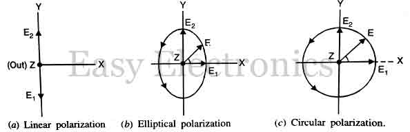
4. Wave Polarization
Wave polarization is defined as the orientation of electric field vector E at a given instant of time in space.
- There are three types of polarization:
- Linear Polarization: A plane electromagnetic wave in which an electric vector vibrates simply harmonically along a fixed straight line perpendicular to the direction propagation without changing its orientation is called a plane-polarized electromagnetic wave.
- Elliptical Polarization: Let us consider the case of two plane-polarized electromagnetic waves which superimpose each other. Now the resultant vector rotates under certain conditions. If both the magnitude and orientation of the electric field vector E vary continuously, then the tip of the vector traces an ellipse. The wave is said to be elliptically polarized.
- Circular Polarization: In the above case, if the magnitude of the resultant vector remains constant but orientation varies continuously then the tip of the vector E traces a circle. The wave is said to be circularly polarized.
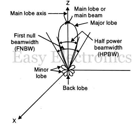
5. Major and Minor Lobes
- The figure shown in the figure has radiation concentrated in several lobes. The radiation intensity in one lobe is considerably stronger than the other. The strongest lobe is called the Major lobe and the other side is the minor lobe.
- In general, maror lobes are those in which the greatest amount of radiation occurs. Side it minor lobes are those in which the radiation intensity is least.
- The level of side lobes should be of the order of 20 to 30 dB below the main beam and it can be achieved easily with the practical antenna. To achieve very low side lobes is quite difficult practically due to limitations imposed by nature but theoretically, there is no reason why it should not be possible.
6. Front-to-Back Ration
- The front-to-back ratio of an antenna is the proportion of energy radiated n the principal direction of radiation to the energy radiated in the opposite direction.
- A high front-to-back ratio is desirable because this means that a minimum amount of energy is radiated in the undesired direction.
7. Beam Efficiency
- Beam efficiency is also an important parameter to judge the quality of the transmitting and receiving antenna.
- In terms of power, the beam efficiency can be defined as the ratio of power transmitted within cone angle 61 to the power transmitted by the antenna and it is dimensionless.
\boxed{\mathbf{Beam\,efficiency=\frac{Power\,transmitted\,within\,cone\,angle\,\theta_1}{Power\,trasmitted\,by\,antenna}}}
- The Beam efficiency should be high usually 90. It is necessary for the antenna used in radar, astronomy, and other applications where reception through the side lobes is not desired.
- In other terms, beam efficiency can be defined as the ratio of the main beam area to the total beam area. It is denoted by \varepsilon_M,
\boxed{\mathbf{ \varepsilon_M=Beam\;efficiency = \frac{\Omega_M}{\Omega_A}}}
where, \Omega_A, is the total beam area solid angle and consists of the main beam (\Omega_M) and the main lobe area (\Omega_m)
Also Read: Radar Display | List of displays used in Radar system
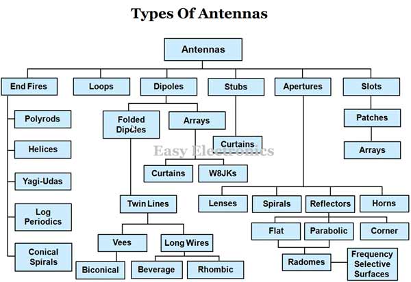
Types of Radar Antennas
- There are many types of antennas are there which we are using in the real world, but all the antennas are not working for Radar systems. For radar systems, some specific types of antennae are used. Some of these will discuss in detail in the later chapters.
- Half-wave Antenna
- Yagi Antenna
- Parabolic Antenna
- Antenna with Consecant squared pattern
- Cassegrain Antenna
- Phased Array Antenna
- Horn Antenna
- Lens Antenna
- Slot Antenna
- Microstrip Antenna
From the above-mentioned antennas, Parabolic antennas are the most important and most helpful antenna in the Radar system.
FAQs on Radar Antenna
What is a radar antenna?
A Radar antenna is a unit that transmits radio waves and receives the echoes of these radio waves.
Which antenna is used in radar?
The parabolic dish antenna
What is radar used for?
Radars are now used to help navigate ships in fog and airplanes in bad weather. Radar can detect a speeding car and track a satellite. Most importantly for meteorologists, radars can detect all sorts of atmospheric phenomena.
What is the range of a radar antenna?
To calculate the range of the radar, please read this article: Radar Range Equation Derivation