
what is instrumentation? what does it deal with?
Answer: The instrumentation is a basic technique that is used to convert physical, chemical & mechanical parameters into known standards of voltage and current.
what is the sensor? how it is different from a transducer?
Answer: It is a device or an instrument that is physically in touch with the process and responds to any change in the physical, chemical or mechanical phenomenon in terms of either change in resistance, capacitance, inductance, or voltage. note- a sensor can be a transducer but a transducer cannot be a sensor.
what is a transducer?
Answer: The basic definition of the transducer is – a device that converts one form of energy to another form, but the broad definition is – a device that converts mechanical or a physical process into an electrical signal, and the reason for transforming into electrical is that electrical signal o/p can be easily used, transmitted and processed for the purpose of measurement. The transducer consists of two elements: sensor + signal conditioning elements.
what is the signal conditioning element?
Answer: It takes the i/p from the sensor and converts it into suitable voltage or current for further processing. basically, it includes a Wheatstone bridge for converting sensor o/p in terms of voltage and then an amplifier, to amplify the o/p voltage for further processing and data storage.
what is the loading effect? what can be done to avoid the loading effect?
Answer: tapping the current from the previous circuit is called loading. this problem occurs when more than one device is connected in a chain. since in instrumentation, devices are connected in the chain only, there is always a chance of loading. generally loading effect occurs at the amplifier stage, so to avoid the loading effect, the amplifier should have high input resistance.
why we transmit information in terms of current, not in terms of voltage in a measurement system?
Answer: We prefer only current transmission not voltage because in voltage transmission series mode interference occurs i.e an unwanted voltage s/g gets added and voltage is corrupted by noise while in the current transmission of information, the current is transmitted to the load escaping from all kinds of interference.
why 4-20mA is preferred over 0-20mA current in industrial automation and why the only the 4-20mA range is considered in industry measurement?
Answer: The reason for considering 4-20mA over 0-20mA is to detect any malfunctioning in wire, at 0mA whether the wire is broken or no signal given, o/p is 0 only but at 4mA, we can detect wire is broken or not. The standard controller needs a digital signal of 1-5volt range with standard resistance of 250ohm for the current of the range 4-20mA. The reason for using 20mA is- the human heart can withstand up to 30mA, so for safety purposes 20mA.
what is the practical application of thermal sensors in industries? give some examples.
Answer: Thermal sensors include-
- RTD
- Thermistors
- Thermocouple
Based on their temperature range of measurement,
1. RTD-It is used in powerplant at different stages ie. refining, power generation condensates, and steam exhaust. it is designed for fast response, so it is put in direct contact to provide close control of the process.
2. Thermistors– can detect a very small range of temp. that could not be detected by RTD or thermocouple. mainly used for temp compensation in Wheatstone bridge circuits. note- thermistors can be installed at a distance from their associated measuring circuits. The application includes- liquid level indicator, flow measurement, thermal switches, and time delay circuits.
3. Thermocouple– used over a wide range of temp. installed in pipelines inside protective wells so that they can be easily removed without interruption or plant shutdown.
How excitation voltage is selected at the signal conditioning stage of the transducer?
Answer: Excitation voltage should not be very high at the signal conditioning stage in Wheatstone bridge because it will result in high power dissipation across the sensor, causing the sensor to damage. so, excitation voltage is always selected according to the sensors’ power dissipation capacity, which is provided by the manufacturer.
How nonlinearity can be reduced in Wheatstone bridge-based thermal sensors?
Answer: for a range of temp., max nonlinearity occurs at its mid-value. to reduce the non-linear error, we can put one or more sensors in common arms. such as, we can use half-bridge circuit. or full-bridge circuit to reduce non-linearity. note- operational amplifier circuit used to remove non-linearity in case of the quarter bridge but sensitivity is compromised while improving linearity.
How operational amplifier can reduce non-linearity in a transducer?
Answer: by using sensors as a feedback element of the op-amp, non-linearity can be completely eliminated.
what is the self-heating effect in thermal sensors? how it can be removed?
Answer: self-heating effect occurs in RTD& Thermistors which is heating of the sensor on applying excitation voltage. as these sensors are temp. dependent, at high temp with given excitation, dissipation across sensor increases by a large amount, can cause damage of sensor, is called the self-heating effect. it can be reduced by reducing the excitation voltage.
What is a strain gauge? types of strain gauge? where do we use these gauges in the industry?
Answer: The strain gauge is a metallic wire, which changes its resistance for the i/p force subjected to it.
Types of strain gauges are:
- unbounded metal strain gauges
- bonded metal wire
- bonded metal foil
- semiconductor-based
- diffused metal strain gauges
- they are used as a secondary transducer in many applications. The application includes measurement of force, weight measurement, load measurement, pressure measurement, torque measurement, and acceleration measurement. these gauges are used in Wheatstone bridge circuit, respond to all these inputs in terms of resistance which is further converted to corresponding voltage and current. they are also used as dummy gauges for temp. compensation.
what are the different types of displacement sensors used in industry?
Answer: The different types of displacement sensors are:
1. resistance-based sensor– example: potentiometers (for large displacement)
2. Capacitive sensors– example: variable area, variable dielectric, and push-pull arrangement.
3. inductive sensors– example: variable reluctance inductive sensors& push-pull inductive displacement sensor. note- inductive sensors have extremely good resolution, hence used for very small range displacement measurement.
why don’t we use the single inductive and capacitive sensor in Wheatstone bridge circuit, unlike resistive sensors?
Answer: we don’t use single capacitive and inductive sensors in WB circuit because o/p voltage will become dependent on input s/g frequency and we will not be able to measure required displacement.
On what principle LVDT works?
Answer: LVDT works on the principle of mutual inductance.
what are the different types of pressure sensors used in industries?
Answer: Variable Capacitance pressure sensor- differential arrangement of the capacitive sensor is extensively used in the process flow industry for monitoring process flow, where sensor o/p is calibrated in terms of pressure difference.
- Strain gauge-based pressure sensors- used for vacuum pressure measurement.
Industrial application of bourdon tube gauges?
Answer: They are used to measure medium to very high pressures. Ex- for measuring high pressure in steam boiler and compressors, for measuring pressure in vehicles tube tire.
what type of flow sensor do we use in the pipeline for liquid flow measurement?
Flow sensors used in pipelines for liquid flow measurement are:
- Ultrasonic flowmeters
- Magnetic flowmeters
- Sonar flowmeters
what is Coriolis flowmeter?
Answer: Coriolis flowmeters use a vibrating tube where the flow of gas can cause changes in frequency, or phase shift proportional to the mass flow rate. At an idle state, the tube vibrates at a predefined frequency. As the fluid flow begins, the vibration of the tube alters proportional to the flow rate of the medium. This change in vibration is measured by sensors across the tube and then translated to flow rate. It is used for corrosive but clean gases. Note- Coriolis flowmeters are highly accurate.
where do we use ultrasonic type flowmeter?
Answer: Industries using ultrasonic flowmeters are – oil and gas, water and wastewater, power, chemical, food and beverage, pharmaceutical, metals and mining, and pulp and paper.
what are mass flow meters?
Answer: A mass flow meter is a way of measuring the volume or mass of a gas or liquid passing through a system at a specific point in the flow system. They are used to measure mass and volumetric flow rates. Mass flow meters have replaced other forms of flow rate measurement because of their accuracy and resolution of flow measurement. Note- there are two types of flowmeter on the basis of measuring technique. 1. Mass flow meter- which measures the mass of liquid and gases to measure their flow rate. Ex-Coriolis, or inertial, and thermal flowmeters 2. Volumetric flow meters- measures the volume of liquid or gas for their flow measurement Ex- ultrasonic, magnetic flowmeters.
Industrial application of Rotameter.
Answer: Rotameters are used widely in the industry to measure both liquids and gas flow rates in plants and are also used for monitoring filtration loading in petrochemical, metallurgy, and light industry.
what is a data acquisition system?
Answer: The data acquisition system (DAS) plays an important role in any monitoring system and is used to collect data from different sensors of a physical variable system. Then, this data is digitalized for storage and the DAS sends data to the control center for processing and presentation.
The basic scheme of DAS is –

What is a flapper nozzle system?
Answer: signal conversion from pressure to mechanical motion and vice versa. This conversion can be provided by a flapper nozzle system (sometimes called a baffle/nozzle system).
What is deadband in the pressure switch?
Answer: The term “dead band” in pressure switches is the difference in pressure value between the setpoint (the pressure at which the switch activates) and the reset point (the pressure at which the switch deactivates). It is sometimes used interchangeably with the terms “differential” or “hysteresis” of a pressure switch. The main purpose of a dead-band in pressure switches is to prevent chattering of the switch by introducing a threshold for when the electrical connection should close and open. Therefore, for a pressure switch to work correctly, it must have a dead band. Example- Imagine a fluid vessel supplying its content to a process stream. The system requires the pump to stop when the pressure is above the setpoint. When the pressure drops back down below the reset point, it will start back up until once again it reaches above the setpoint, Without a dead band, the switch will start and stop the pump continuously as the measured pressure goes above and below the setpoint. This is an undesired condition that could damage the pump. By setting a dead band (or reset point), a differential is created between when the pump is stopped and when the pump is started. This simple solution prevents the continuous start and stop of the pump, thereby extending its useful life
Why do we use three-wire in RTDs?
Answer: To compensate for the effect of lead resistance, we use three-wire RTDs. The 3 wire construction of an RTD is the most common type where one side of the element has one wire connected and the other side has two wire connections. This allows for the extra resistance created in the circuit to be compensated for giving a more accurate reading.

- The resistance is calculated by first calculating the resistance between wires 1 and 2 and then subtracting the resistance between wires 2 and 3 which results in an accurate measurement for the resistance element (Rb). This method assumes that all wires are measuring the same resistance; they, therefore, have to be identical.
what is the effect of vapour pressure in orifice plate flow measurement?
Answer: For gas and vapour flows, the true flow rate deviates even more from the theoretical (ideal) flow value than liquids do, for reasons that have to do with the compressible nature of gases and vapours.
- A gas expansion factor (Y ) may be calculated for any flow element by comparing its discharge coefficient for gases against its discharge coefficient for liquids.
- As with the discharge coefficient, values of Y for any real pressure-generating element will be less than 1:
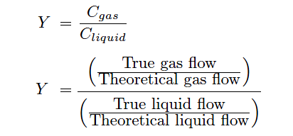
- Incorporating these factors into the ideal volumetric flow equation we arrive at the following formulation:
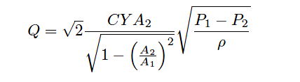
- neither the discharge coefficient (C) nor the gas expansion factor (Y ) will remain constant across the entire measurement range of any given flow element. So, there will be more fluctuation in flow measurement, which can be removed if we know the values of C and Y for typical flow conditions, we may achieve good accuracy most of the time.
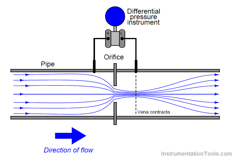
which is more effective pressure sensors or one single differential pressure sensor in orifice plate measurement?
Answer: Orifice plates determine flow by measuring the difference between the upstream pressure and the downstream pressure by using a differential pressure transmitter.
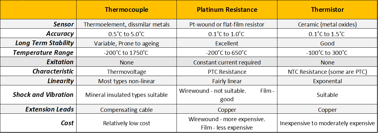
How many types of thermocouples are there? How many leads are there in thermocouple measurement?
Answer: The thermocouple’s temperature range and sensitivity are dictated by the combination of alloys that make up the sensor (ex. J-type, K-type, etc.). For a list of the most common thermocouple types.
Thermocouple types and properties
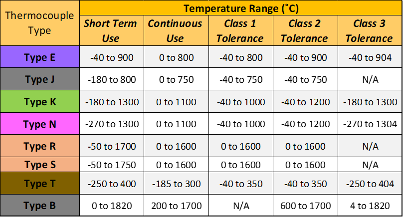
- Thermocouples are constructed from two wire leads made from different metals.
Different types of RTDs and their properties
Thermocouple sensor types and their respective properties
How pressure sensors are connected in level measurement in the differential pressure method?
Answer: A differential pressure transmitter calculates the level by measuring the differential pressure between the liquid and the gaseous phases of the fluid inside a closed tank. For precise calculations, important factors include:
- The geometry of the tank (horizontal or vertical, shapes of various lids and bottoms, etc.)
- The specific density of the medium
- Hydrostatic pressure
- The distance between points H and L in a tank is necessarily much longer than in a pipeline, necessitating the use of tubing to bridge that distance (Figure). But not just any size of the tube will do. For accurate measurements, these small pipes – capillaries, really – have to be so thin and limited in volume that they transmit media without any changes in pressure.
- However, using capillaries creates its own set of challenges. Within an enclosed system, the pressure of a gas is directly proportional to its temperature. This is Gay-Lussac’s Law. In larger pipes, an increase in temperature/pressure won’t have much effect on differential pressure readings. But within the confines of a capillary, any changes in temperature and, thus, pressure are magnified. Measurement solutions with this kind of connection to the measuring points are sensitive to temperature.
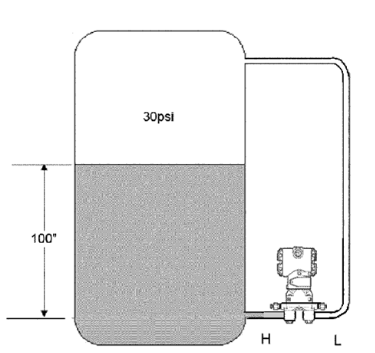
- Differential pressure transmitter configured to measure level inside a tank.
What is the output of the capacitive pressure sensor (ac or dc), how its o/p is signal characterized?
Answer: Capacitive pressure sensors output is AC only, it does not allow DC to pass through it.
o/p is a signal characterized by many different ways-
- By connecting the capacitive sensor in op-amp ckt directly.
- By connecting it in Wheatstone bridge ckt.
- The change in capacitance can also be measured by connecting the sensor in a frequency-dependent circuit such as an oscillator or an LC tank circuit. In both cases, the resonant frequency of the circuit will change as the capacitance changes with pressure.
What is the physical meaning of the discharge coefficient? Why it is calculated? An orifice plate what is its value, why is less it than 1?
Answer: A discharge coefficient is a dimensionless number used to characterize the flow and pressure loss behavior of nozzles and orifices in fluid systems.
- discharge coefficient (cd) is calculated as a final modifying factor in the flow rate equation. Its use should counteract errors due to assumptions made while developing a model. The ideal assumption of discharge coefficient while calculating flow rate is 1, so while measuring flow rate due to different varying factors, this coefficient value will always be less than 1. These factors are Reynolds number, pressure differential, gas expansion factor, choke shape, etc.
Q at upstream is equal to or not equal to Q at downstream of orifice plate why?
Answer: As there is always a permanent pressure loss at vena contracta, so flow upstream is not going to be equal to the pressure downstream.
What is vena contracta in orifice plate?
Answer: Vena contracta is the place where the fluid flow has the smallest cross-sectional area and lowest pressure. It depends on the flow rate and pipe size. It is designed to achieve maximum Differential pressure.
why rotameter is called a variable area flowmeter? Can it measure flow even if the area is not varying? why it is made tapered?
Answer: The rotameter’s operating principle is based on a float of given densities establishing an equilibrium position where, with a given flow rate, the upward force of the flowing fluid equals the downward force of gravity. It does this, for example, by rising in the tapered tube with an increase in flow until the increased annular area around it creates a new equilibrium position
- so, it can measure flow rate only when the area is varying and it is made tapered shape to vary the annular area. The tapered tube’s gradually increasing diameter provides a related increase in the annular area around the float, and is designed in accordance with the basic equation for volumetric flow rate:
Q= kAsqrtgh
Q = volumetric flow rate, e.g., gallons per minute
k = a constant
A = annular area between the float and the tube wall
g = force of gravity
h = pressure drop (head) across the float
Why thermocouple is connected in parallel and series?
Answer: Thermocouples can be connected electrically in series or in parallel. When connected in series, the combination is usually called a thermopile, (whereas there is no particular name for thermocouples connected in parallel). The total output from n thermocouples will be equal to the sum of the individual emf’s. The main purpose of using a thermopile rather than a single thermocouple is to obtain a more sensitive element. Parallel connection of thermocouples is used for averaging.
Which is more sensitive pt100 or pt50?
Answer: The most common platinum PRT sensor used in the process industry is the Pt100 sensor. The number “100” in the name indicates that it has a resistance of 100 ohms in 0°C (32°F) temperature, while pt50 has a resistance of 50ohm at the same temperature. They both have the same level of sensitivity for temperature as a temp. is kept constant here.
Also Read: