In this lecture, we are going to discuss the Non-Inverting Operational Amplifier. We will discuss the operation of a non-inverting Op Amp, the derivation of the closed-loop voltage gain of the non-inverting operational amplifier, and input and output resistance.
There are three basic op-amp configurations:
- Inverting operational amplifier
- Non-inverting operational amplifier
- Buffer amplifier or Voltage follower
Note that the Non-inverting operational amplifier configuration discussed in this section, we assume that the used operational amplifier in this section is ideal.
Non-Inverting Operational Amplifier
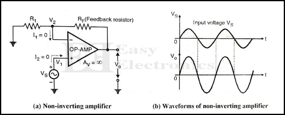
The non-inverting operational amplifier using Op-amp is shown in the below figure. Here the signal that is to be amplified is applied to the non-inverting (+) terminal of the Op-amp.
As shown in the figure, the input and output voltages are in phase with each other.
The negative feedback is incorporated in this circuit CIA the feedback resistor RF which is connected between the output and inverting terminal of Op-amp.
Assume the op-amp is ideal.
Closed Loop voltage gain of Non-inverting Op-amp
As we are using the ideal op-amp, Ri = ∞. Therefore the current entering into both the input terminals of op-amp will have a zero value. (I1 = I2 = 0)
Therefore voltage across R1 is given by,
\mathbf{{V_2 = \frac{R_1}{(R_F + R_1)}V_0}}
As per the virtual short concept discussed earlier,
V2 = V1 = Vs
\therefore \mathbf{{V_s = \frac{R_1}{(R_F + R_1)}V_0}}
Therefore the closed loop voltage gain AVF is given as,
\mathbf{A_{VF} = \frac{V_0}{V_s} = \frac{R_1 + R_F}{R_1}}
\therefore \boxed{\mathbf{A_{VF} = 1 + \frac{R_F}{R_1}}}
Conclusions from the Expression of AVF:
- The positive sign of the equation indicates that the input and output are in phase with each other.
- The closed-loop control gain is always greater than unity (1).
- AVF is adjustable and its value can be adjusted by varying the values of RF and R1. Generally, a variable resistor is used in place of RF to adjust the closed loop gain to its desired value.
- AVF is independent of the open loop gain of the op-amp. It depends only on the values of RF and R1.
Ideal Closed Loop Characteristics of Non-inverting Op Amp
We have already obtained the expression for closed loop gain of the non-inverting operational amplifier. Let us now obtain the values of closed-loop input and output resistances.
Closed loop input resistance RiF
- The closed loop input resistance of the non-inerting op-amp can be obtained from the ideal equivalent circuit shown in the figure below.
- The closed loop input resistance RiF is the resistance seen by the source between the non-inverting (+) terminal and ground.

- Due to the infinite input resistance (Ri = ∞) of the ideal op-amp the non-inverint (+) terminal appears as an open circuit.
∴ RiF = ∞
- Note that the input resistance is ∞, and not R1 as for the inverting amplifier. This is the advantage of using the non-inverting amplifier.
Closed loop input resistance RoF
- As the ideal op-amp is being used, its output resistance R0 = 0. Hence the output resistance of the closed loop configuration is 0.
∴ R0F = 0
FAQs on Non-inverting Op Amp
What is a non-inverting operational amplifier configuration?
The non-inverting operational amplifier configuration is a common setup in electronics where the non-inverting terminal (+) of the op-amp is connected to the input signal, and the inverting terminal (-) is connected to a voltage reference or ground.
How does a non-inverting op-amp work?
A non-inverting op-amp amplifies the input signal by a factor (1 + Rf/Rin), where Rf is the feedback resistor and Rin is the input resistor. It provides a positive gain and is used for signal amplification.
What are the key advantages of the non-inverting op-amp configuration?
The advantages include a high input impedance, simple circuit design, and the ability to provide voltage amplification with a non-inverting output.
What is the input impedance of a non-inverting op-amp?
The input impedance of a non-inverting op-amp is very high, typically close to infinity, making it ideal for interfacing with high-impedance sources without loading them.
What are some practical applications of non-inverting op-amp circuits?
Non-inverting op-amp circuits are commonly used in audio amplifiers, voltage followers, signal conditioning, and analog signal processing.
Are there any limitations or drawbacks to using non-inverting op-amp configurations?
While non-inverting op-amp circuits offer many advantages but they may not be suitable for applications that require a negative gain or differential amplification.