In this lecture we are going to learn Analog to Digital converter (ADC) in very detailed manner. We will also learn each ADC with detailed analysis. So lets start from the definition of ADC.
Definition of ADC (Analog To Digital Converter)
ADCs convert an analog signal input to a digital output code. Basically it converts physical variables which are analog in nature to digital signal for processing. They have high conversion efficiency and requires less power. Examples of physical variables include audio signals, temperature, pressure etc.
ADCs performance specifications are generally categorized in two ways:
- Accuracy.
- Dynamic performance.
Types Of ADC (Analog To Digital Converter)
The types of ADC are as per the following:
- Counter type/ Ramp type ADC.
- Successive approximation type ADCs.
- Flash type ADCs.
- Dual slope ADCs.
Now we will discuss the each ADC in detail.
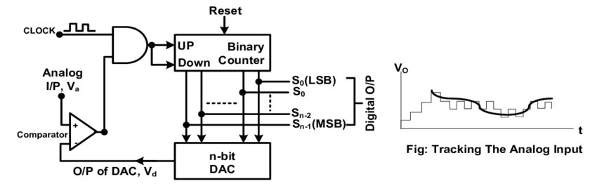
1. Counter type ADC:
A comparator is used at the input to compare input analog voltage with feedback reference voltage provided by DAC. An up/down counter is used to count the number of clock pulses applied through AND gate.
When conversion started , counter is reset to zero and input analog voltage is applied to terminal of the comparator, when analog voltage is greater than feedback voltage provided by DAC, comparator o/p is logic 1 due to which clock pulses are applied to counter & counter will increase counting.
When analog voltage is less than feedback voltage then o/p of comparator is logic 0 and counter will stop. At this time, o/p of counter will provide binary equivalent of i/p analog voltage.
Note: In an n-bit counter type ADCs, maximum number of clock pulse used is 2n-1.
In this type of ADCs, conversion time linearly varies with i/p analog voltage.
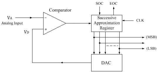
2. Successive approximation type ADC | SAR ADC
- In this type of ADC, comparator is used to compare the input analog voltage with feedback reference voltage provided by DAC same as counter type ADCs but here we use ring counter to successively set one by one bit from MSB to LSB with clock.
Step-1: The MSB is initially set to 1 with the remaining three bits set as 000. The digital equivalent voltage is compared with the unknown analog input voltage.
Step-2: If the analog input voltage is higher than the digital equivalent voltage, the MSB is retained as 1 and the second MSB is set to 1. Otherwise, the MSB is set to 0 and the second MSB is set to 1.
- Let us assume that the 4-bit ADC is used and the analog input voltage is VA = 11 V. when the conversion starts, the MSB bit is set to 1.
Now VA = 11V > VD = 8V = [1000]2
- Since the unknown analog input voltage VA is higher than the equivalent digital voltage VD, as discussed in step (2), the MSB is retained as 1 and the next MSB bit is set to 1 as follows
VD = 12V = [1100]2
Now, VA = 11V < VD = 12V = [1100]2
- Here now, the unknown analog input voltage VA is lower than the equivalent digital voltage VD. As discussed in step (2), the second MSB is set to 0 and next MSB set to 1 as
VD = 10V = [1010]2
Now again VA = 11V > VD = 10V = [1010]2
- Again as discussed in step (2) VA > VD, hence the third MSB is retained to 1 and the last bit is set to 1. The new code word is
VD = 11V = [1011]2
- Now finally VA = VD , and the conversion stops.
- In SAR type ADC, conversion time is independent on input analog voltage and depends on number of bits only.
So for n- bit conversion, maximum no. of clock pulse is n.
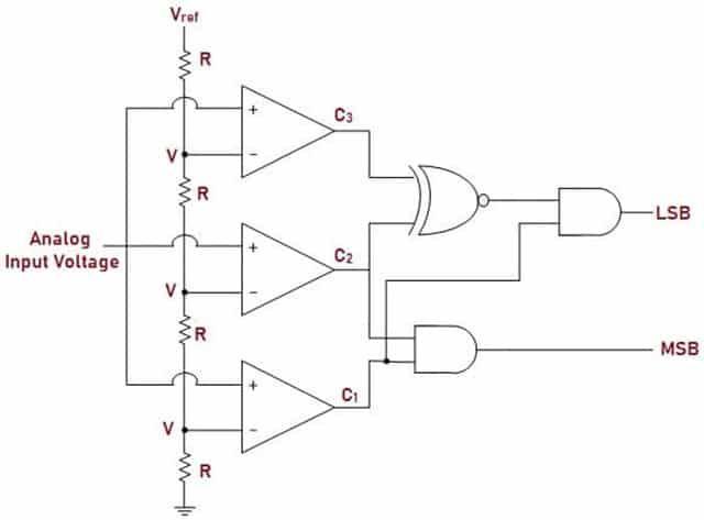
3. 3-bit flash ADC | Flash type ADC
- It is the fastest ADC. In this type, number of comparator are connected in parallel to increase the speed of operation, hence also known as parallel comparator type ADC.
For n-bit conversion maximum 2n-1 comparators are connected and for n-bit conversion maximum one clock pulse is required.
- Figure below illustrates block diagram of Analog to Digital Converter (ADC) where Analog input is connected to all comparators so that the output is generated simultaneously.
- Reference Voltage (Vref) is supplied to the Comparator through external source.
- The Digital output from the Comparators acts as input to Encoder. The Encoder converts the code from Comparator to Binary Code.
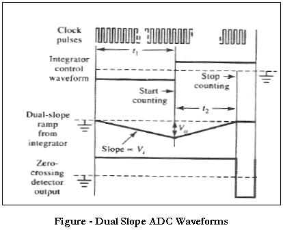
4. Dual slope ADC
It is the most accurate ADC but the slowest one.
In this type, an integrator is used to integrate the analog voltage and negative reference voltage. When conversion started ,counter and T Flip flop are set to 0 and switch is connected to analog voltage. During analog voltage integration, o/p is negative, due to which comparator o/p is logic 1 and counter will continuously increase .after 2n clock pulse, counter will reach 0 again, at this time T flip flop toggle to 1 and switch become connected to negative reference voltage.
During reference voltage integration, o/p of integrator is logic 1 between time interval t1 and t2, hence counter will count the pulses for the second time. When t > t2 , comparator output is logic 0 and counter will stop.
Maximum number of clock pulse = 2n+1

\frac{V_{ref}}{RC} \times t_2 = - \frac{V_A}{RC} \times t_1
t_2 = -\frac{V_A}{V_{ref}} \times t_1
V_A= - \;V_{ref} \times \frac{t_1}{t_2}
Applications of ADC
- Dual slope type ADC is used in digital multi-meter and digital oscilloscope.
- Almost all modern microcontrollers have a built in ADC, the most common being the Arduino based on the ATMega328P with a 10 bit resolution and the STM32 with a 12 bit resolution.
- Most power supplies these days are computer controlled, and for the computer to measure the voltage output an ADC is needed.
- They are used in Audio/Video devices.
- They are used in Cell Phones.
Advantages of ADC
- The advantages of Analog to Digital Converter include:
- Flash ADCs are the fastest compared to the other Analog to Digital Converter.
- Dual slope type ADCs are most accurate one .
- Successive Approximation ADCs operate at high speed and are more reliable.
Disadvantages of ADC
- The disadvantages of ADCs are:
- Circuit Complexity increases with the increase in the use of Comparators in Flash ADCs.
- Flash ADCs are expensive.
- Successive Approximation converters used for higher resolution will be slower.
- Dual slope type ADCs are slowest one.
Frequently Asked Questions on ADC
-
Which is an example of analog to digital converter?
Answer: Analogue-to-Digital Converters, (ADCs) allow micro-processor controlled circuits, Arduinos, Raspberry Pi, and other such digital logic circuits to communicate with the real world.
-
What is the use of analog to digital converter?
Answer: An analog-to-digital converter (ADC) is used to convert an analog signal such as voltage to a digital form so that it can be read and processed by a microcontroller. Most microcontrollers nowadays have built-in ADC converters. It is also possible to connect an external ADC converter to any type of microcontroller.
-
How does ADC convert analog to digital?
Answer: ADCs follow a sequence when converting analog signals to digital. They first sample the signal, then quantify it to determine the resolution of the signal, and finally set binary values and send it to the system to read the digital signal. Two important aspects of the ADC are its sampling rate and resolution.
-
Why we use ADC & DAC?
Answer: Analog to Digital Converter (ADC) and Digital to Analog Converter (DAC) are very important components in electronic equipment. Since most real world signals are analog, these two converting interfaces are necessary to allow digital electronic equipment to process the analog signals.