
Power Amplifiers
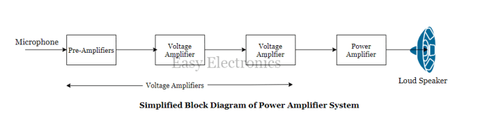
To deliver a large power to a load, a specially designed amplifier called a “Power Amplifier” is used as a final stage as shown in the figure below.
It is called the “Large Signal Amplifier” because it is capable of supplying an adequately large amount of power to the load like a loudspeaker.
The primary aim of a power amplifier is to supply a large power therefore the voltage gain is not important.
Power amplifiers are used as the last stage in the P.A system, radio receivers, TV receivers, etc.
Some of the important features of power amplifiers are as follows:
- Impedance matching with the load is necessary for the maximum transfer of power.
- They use power transistors.
- Power amplifiers are bulky due to the use of heat sinks.
- Harmonic distortion is present in the output.
- They are capable of handling a large power.
Depending on the position of the Q-point or operating point on the load line, the Power amplifiers are classified into the following four categories:
- Class-A amplifiers
- Class-B amplifiers
- Class-C amplifiers
- Class-AB amplifiers
Read More: Classification of Different Amplifier
This classification has been done on the basis of the Q-point on the load line.
The types of amplifiers and the position of the Q-point are listed below table:
| Sr. NO | Type of amplifier | Position of Q-point |
|---|---|---|
| 1. | Class-A | At the center of the load line |
| 2. | Class-B | In the cutoff region |
| 3. | Class-AB | Just above the cutoff |
| 4. | Class-C | Below the cutoff |
Class-A Power Amplifier
- An amplifier is referred to as a class A amplifier if the transistor used for amplification conducts for the full cycle duration of the input ac signal.

- The Q-point is adjusted exactly at the center of the load line as shown in the figure below.
- Due to this, the output signal is obtained for the full cycle of the ac input. i.e. 360o.
- The power transistor is biased such that the operating point (Q-point) is approximately at the center of the load line.
- Now, when we apply the ac signal to the base of the power transistor, the base current changes sinusoidally above and below the quiescent base current IBQ.
- In response to the changes in IB, the collector current changes sinusoidally above and below its quiescent current value ICQ. The collector current and base currents are in phase with each other.
- Due to changes in IC, the voltage VCE will also fluctuate sinusoidally.
Note: VCE and IC are 180o out of phase.
Operation of Class-A Power Amplifier

- The transistor remains in the “active region” for all the values of the input signal and never enters into the saturation or cutoff regions. So class-A power amplifiers are linear amplifiers.
- The transistor conducts the complete cycle of ac input i.e. for 360°. Thus the angle of collector current flow is 360° or a full cycle.
- As shown above figure, the input signal is amplified faithfully, without introducing any distortions. Thus harmonic contents in the output will be low.
- As the transistor continuously operates in its active region, the voltage VCE across it and current Ic. through it, both are simultaneously high.
- Therefore a large power will be dissipated in the transistor in the form of heat.
- Therefore the efficiency of class A power amplifiers is low. In fact, it is the lowest of all the power amplifiers.
- Typically the efficiency (n) of a class A power amplifier lies between 25% to 50%.
Advantages of class A power amplifier
- Simple construction.
- Distortionless output voltage.
Disadvantages of class A power amplifier
- Very low efficiency (25% or 50%)
- Large power dissipation in the power transistors.
Class-B Power Amplifier
- An amplifier is referred to as a class B amplifier if the output signal is obtained only for one half-cycle period of the input ac signal.

- The transistor conducts only in a one-half cycle of the input and the collector current, therefore, flows for only 180°, as shown in the below figure.
- For this, the Q point is adjusted to be a cut-off. i.e. on the X-axis as shown in the below figure. Thus in the absence of an ac input signal, the transistor remains in the off state.
- The coordinates of the Q-point are (Vcc, 0).
Operation of Class-B power amplifier

- As we apply a sinusoidal input signal to the base of the transistor, the B-E junction of the transistor is forward-biased only during the positive half cycle of the input and the base current starts flowing.
- The transistor remains in the active region, only for the positive half cycle of the input signal In the negative half cycle, the transistor remains in the off state. Thus collector current flows for only 180° (half cycle) of the input signal.
- As seen from the above figure, only one-half cycle is obtained at the output. Therefore the output voltage waveform is distorted because it is no more a sinewave.
- The distortion can be eliminated by using two transistors in alternate half cycles of the input signal to produce the complete cycle of the signal at the output. Each transistor conducts only 180°. This is called the push-pull class B power amplifier.
- As the transistor remains off for the complete negative half cycle, the power dissipation in the transistor is reduced as compared to that in the class A power amplifier.
- Therefore the efficiency of class B amplifiers is higher than that of class A power amplifiers.
- The maximum efficiency of the class-B configuration can be 78.5% which is much higher than that of the class-A power amplifier.
Crossover Distortion
- The waveform distortion near the zero-crossing points is observed in class B power amplifiers.
- This happens because the transistors are biased at cut-off.
- The crossover distortion can be eliminated by using the class-AB type power amplifier.
Advantages of class B power amplifier
- Higher efficiency (78.5%)
- Zero power dissipation under quiescent conditions.
- Impedance matching with load is possible.
- The second harmonic component gets automatically canceled.
Disadvantages of class B power amplifier
- Crossover distortion is present in the output waveform.
- Efficiency is not so high.
Class-AB Power Amplifier
An amplifier is referred to as a class AB amplifier if the output signal is obtained for more than 180o but less than 360o of the ac input signal.

That means the power transistor connected in a class AB power amplifier will conduct for more than 180o but less than 360o of the ac input.
For this, the Q-point is positioned slightly above the cutoff. Thus in absence of an ac input signal, the transistor is “Just conducting”.
Operation of Class-AB Power Amplifier

- In order to obtain the output signal for more than 180° and less than 360° of the ac input signal. the Q point is positioned slightly above the X-axis but below the mid-point of the load line.
- The transistor conducts for the complete positive half cycle and a part of the negative half cycle of the input signal.
- The output signal is distorted. However, this distortion can be eliminated by using two transistors which can conduct in the alternate half cycles of the input. The class AB operation is helpful in eliminating cross-over distortion.
- The Q point is neither in the middle of the load line like the class A operation nor on the X-axis like class B. It is in between the two. Therefore the name class AB operation. The transistor conducts for more than 180° (class B) but less than 360° (class A), therefore the power dissipation in the transistor is less than that in class A operation and more than that in the class B operation.
- Hence the efficiency of the class AB power amplifier is higher than class A but less than the class B power amplifier.
Advantage of class AB power amplifier
- The biggest advantage of class AB amplifiers is the elimination of crossover distortion.
- Hence this configuration is preferred in all audio systems, radio, TV receivers, etc.
Class C Power Amplifier
- An amplifier is referred to as a class C power amplifier if its output is obtained for less than a half-cycle period of the input ac signal.

- Thus the power transistor in a class C configuration will conduct for a duration that is less than the period of a half cycle of the ac input signal.
- For this, the operating point is adjusted to be below the X-axis as shown in Figure below. Thus the transistor is biased below the cut-off.
Operation of Class C Power Amplifier

- Due to the biasing below the cut-off, the transistor can remain in the active region for less than a half-cycle period. Thus collector current flows for less than 180°. In other words, the conduction angle is less than 180°.
- Due to the reduced conduction angle, the output signal is heavily distorted. The percent distortion is higher than that for a class B power amplifier. Therefore class C power amplifiers are not used as A.F. power amplifiers.
- The efficiency of class C amplifiers is very high. In fact, it is the highest of all the power amplifiers.
- Typically the efficiency is above 95%.
Advantage of class C power amplifier
- Very high efficiency (higher than 95%).
- Low power loss in the power transistors.
The disadvantage of class C power amplifier
- The output waveform can be distorted.
Applications of class C power amplifier
- Class C amplifiers generally use a tuned circuit as a load. Such amplifiers are called class – C tuned amplifiers.
- These amplifiers are used as the collector modulator to produce the amplitude-modulated signal.
comparison of power amplifiers
| Sr. No | Parameter | Class A | Class B | Class C | Class AB |
|---|---|---|---|---|---|
| 1. | Conduction angle of collector current | 360o or full-cycle | 180o or half cycle | Less than 180o | Between 180o and 360o |
| 2. | Position of Q-point on the load line | At the center | On the X-axis | Below the X-axis | Above the X-axis but below the midpoint |
| 3. | Distortion in output voltage | No distortion | More than class-A (Crossover) | More than A, B, and AB | Low |
| 4. | Efficiency | Lowest 25% to 50% | Higher (78.5%) | Very High(95%) | Between 50 and 78.5% |
| 5. | Power dissipation in transistors | Very high | Low | Very low | Moderate |